Electronic components give off heat by emitting infrared radiation. This radiation can be absorbed by neighbouring components or the environment (e.g. heat sink, housing) and then dissipated further. How much the heat radiation contributes to cooling depends on various factors. In addition to the distance and angle between the radiating partners and the temperature difference, the surface condition also plays a role. Since we are dealing with infrared wavelengths, the colour of the surface has no influence. A reflective metallic surface can hardly radiate heat, while a raw, slightly oxidised metal surface with an emissivity of 0.2 (a dimensionless number describing the surface finish on a scale of 0 to 1) can participate noticeably in the radiation exchange. A painted or powder-coated surface radiates heat about four times more than a slightly oxidised bare metal surface.
To complete the overview, thermal radiation in the visible light spectrum should also be mentioned. This plays an important role for all outdoor devices. Since solar radiation, weakened by the atmosphere and by the angle to the earth’s surface, can represent an additional heat load, outdoor equipment should always be painted or powder-coated in light colours. Depending on the size of the object and its surface (e.g. a charging station for e-mobility), choosing the wrong colour can increase the temperature of the device by around 10 to 15 Kelvin.
Transfer of these physical parameters into an electronic design
Based on the typical heat sources, such as electronic components with their switching losses, inductive heat sources in winding goods or the heat load due to high currents in copper rails or conductor tracks, it is of crucial importance to find an adequate solution for heat management.
Once the layout of a circuit board has been determined and already integrated into a final design model, a device failure due to thermal overload can only be corrected at considerable cost. Therefore, it is essential to consider some fundamental aspects of future heat management as early as the design phase.
The following aspects should be considered when planning the circuit board, the functional groups and the selected electronic components:
- Are there alternative electronic components that produce less heat loss?
- Are electronic components with optimised heat paths and connection surfaces available?
- Is the subsequent air flow in the device known and can larger electronic components contribute to air conduction?
- Could heat-sensitive components be shielded from the cooling air by large capacitors, transformers or plugs?
- Should strong hot spots be physically separated from sensitive components on the PCB?
- How can heat absorption and distribution over the PCB be optimised?
- Use thicker signal layers and copper inlays
- Fill unused areas in the signal layer with copper
- Use thermal vias or screw points as a bridge to thicker inner layers or to heat sinks on the opposite side of the PCB
- Use the path combination ‘via->inner layer->via->wedge lock clamp on metal housing’
- Is it a disposable product or should it be easy to maintain (device encapsulation for heat dissipation?)
- Is there space for a heat sink and can cooler supply air be directed into the fin spaces?
- Are critical weight specifications to be observed?
- In which orientation will the circuit board be mounted and are there any sensitive components ‘above’ powerful heaters?
- Could a heat pipe still work efficiently with the intended direction of gravity?
- Is the use of a fan planned?
- Where should the fan be installed (sucking or blowing)?
- What volume flow should the fan be able to generate against the system pressure to dissipate a targeted amount of heat?
- Is an air grille or filter required that would further restrict the air volume?
- Can the housing be made of metal or plastic?
- Are there any external heat sources in the subsequent place of use?
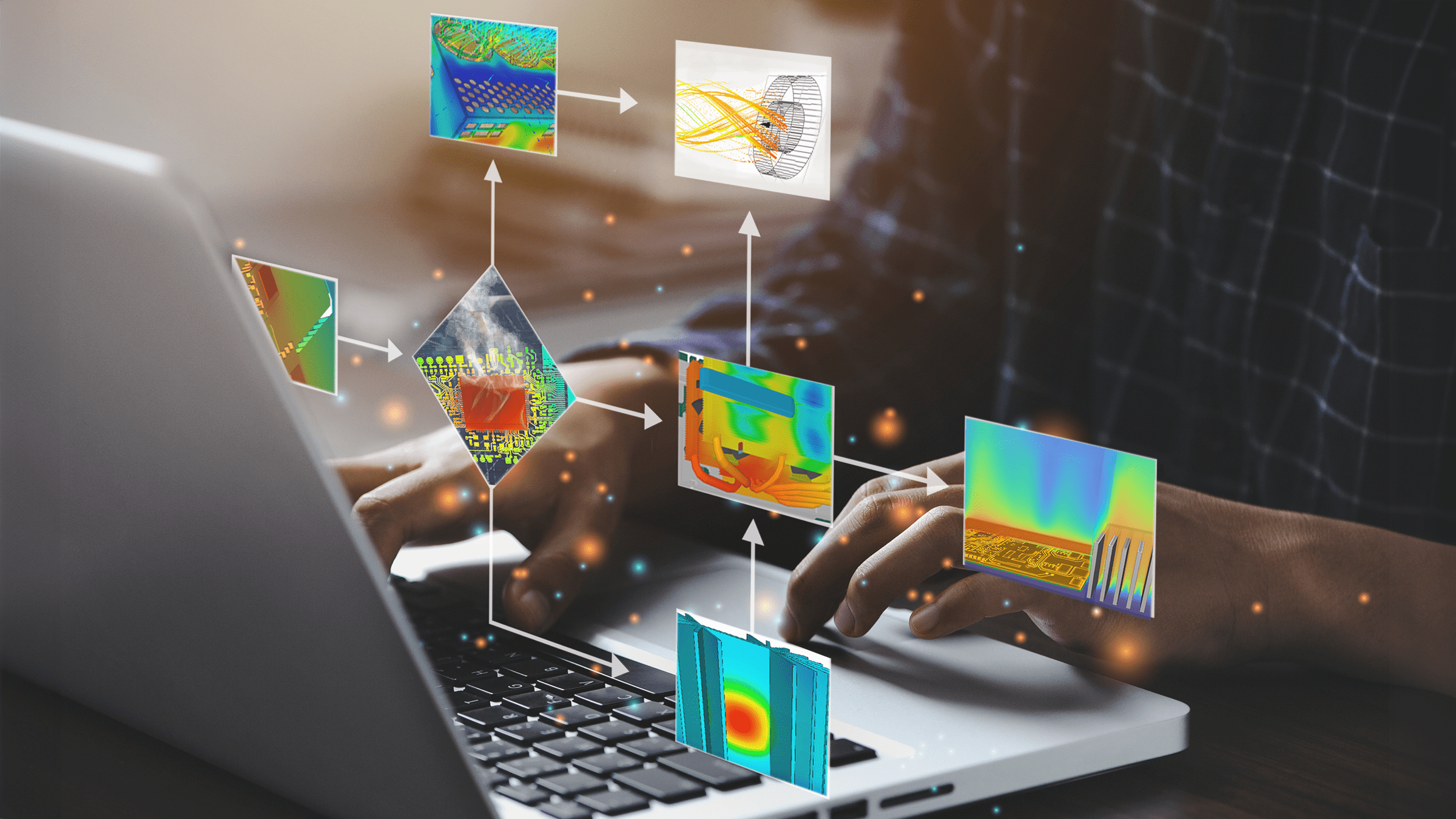
During the development cycle, increasingly detailed information is available to optimise the efficiency of heat dissipation. Advanced 3D simulation tools such as CelsiusEC from Cadence are ideal for this. These make it possible to create physically precise models of printed circuit boards, components and device structures with just a few input data, even in the concept phase, and to visualise all three mechanisms of heat transfer.
ALPHA-Numerics GmbH offers a comprehensive training programme for engineers working in this area of development. Particular emphasis is placed on teaching the scientific principles in a practical way and applying them directly.


