6SigmaET Release 16 – Whats New?

by | Jan 17, 2022 | News

6SigmaET is a CFD software tailored for the development of electronic devices. It enables the developer to predict the thermal challenges and to check the resulting solution concepts simulatively, from PCB conception through CAD-based enclosure design to the virtual prototype. Such specialised software continues to evolve through annual releases. Usually, customers’ functional wishes or functional requirements of new markets are the innovation drivers for the software manufacturer.

Release 16 focuses on the bottleneck of all CFD software on the market: speed without compromising the quality of the simulation results!
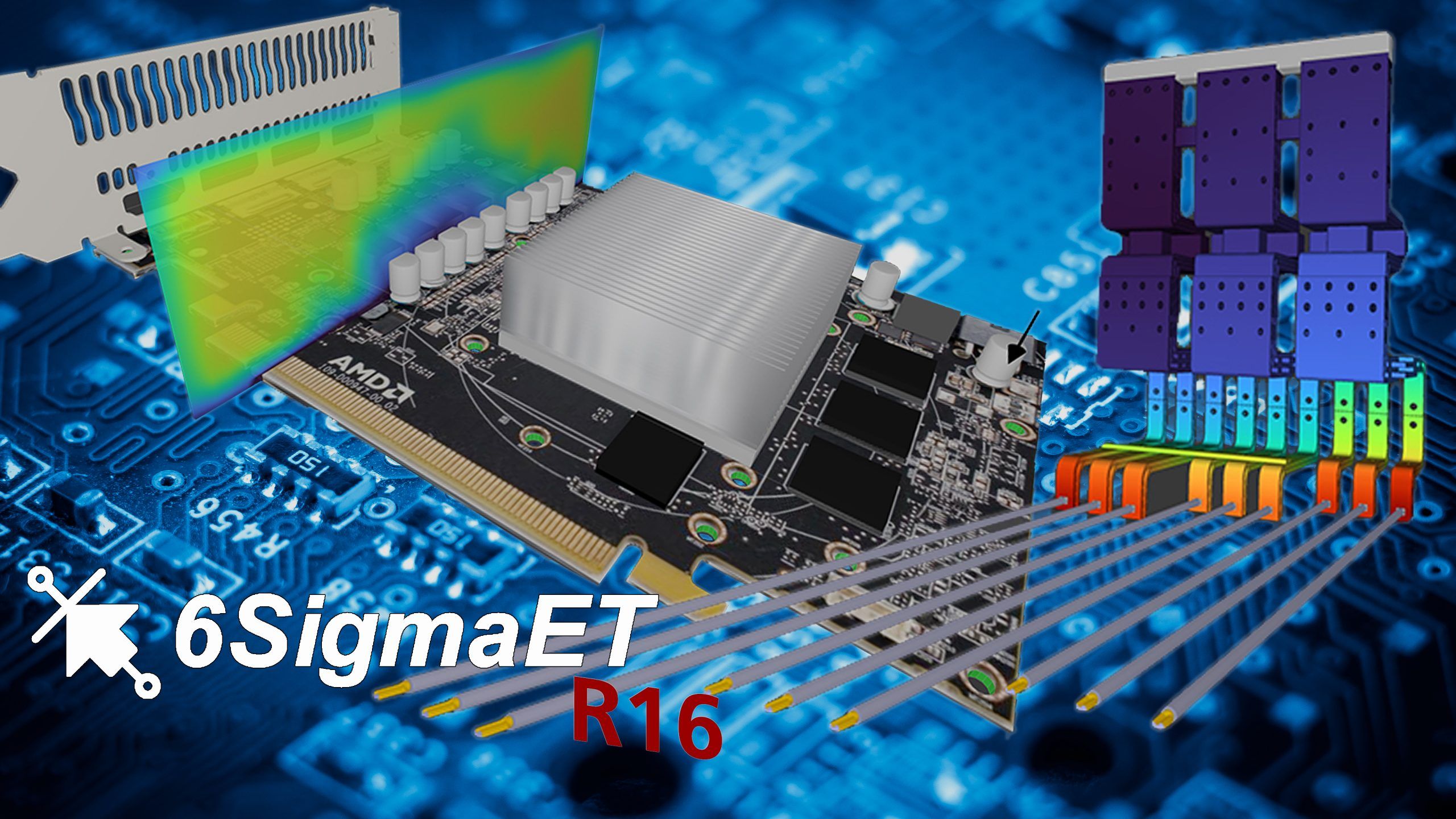
6SigmaET already had the unique selling point of being able to handle a very large amount of detail (up to 700 million solution cells possible) of CAD data and PCB details in its simulations on normal Windows workstations.

In addition to the ease of creating such models, the speed of the solver has also been very impressive. For example, it is not uncommon for the CFD solver to calculate 80 million cell projects overnight until convergence (the temperature behaviour based on thermal conduction, convection and thermal radiation in steady state) and provide the engineer with the results the next working day.

However, the complexity of the tasks has grown considerably in recent years. New electronic devices not only have to incorporate more and more functions in a smaller installation space. No, they also have to cope with higher ambient temperatures, high IP protection classes and possibly integrated energy concepts in a wide range of extreme conditions.

Thus, a standard simulation with clear power dissipation carriers on a PCB and a simulated result in steady state does not provide enough meaningful details for the evaluation of a successful cooling concept.

New factors and details have been increasingly incorporated into simulation models in recent years.

These include:

  • Detailed shading situations for thermal radiation in the units (hotspot due to radiation transfer with partial shading).
  • In addition to thermal vias through the PCB, now special grids of micro-vias or bured vias between defined inner layers
  • Fully detailed power components with bonding and real CAD package geometry and pin connection to the PCB
  • Live conduction structures, be it multilayer PCBs or copper bars with fuses and shunts for Joule calculation of heat losses in metal
  • Transient observation of temperature curves in warm-up, cool-down or cycled situations.
  • Different surface qualities of large CAD enclosure bodies ( e.g. blank inside, painted outside)
  • Heat influence of solar radiation or altimeter on the test specimen
  • Fluid coolers with micro-turbulators as a detail in the overall device simulation
  • Detailed insulation bodies in electric motors and heat barriers

etc.

6SigmaET Release 16 offers many important new features to integrate all these details in a single simulation and not block an engineer’s working time with long waiting times during the modelling of the calculation or the evaluation phase.

After all, the software manufacturer has been working closely with the market leader for graphics performance, the company Nvidia, for 1 year now. Here, the company relies on the CUDA technology of its powerful graphics cards.

6SigmaET has been able to set itself at the top of the industry-specific CFD tools in the electronics industry for quite some time due to its performance and thus the handling of many details in a simulation model. However, the integration of the GPU into the GUI (Graphical User Interface = user interface of the software) and the outsourcing of various computational processes before the CFD solvent have immensely accelerated the working speed with 6SigmaET.

The following overview of the highlights from Release 16 should give you a first impression of the areas in which the release focus “acceleration” could be implemented this year:

  • The user interface is now accelerated directly by the GPU for the most part.
    • Construction window reacts much faster when modelling
    • Graphic representation of the models looks very realistic
    • Calculated surface temperatures are projected onto the model more quickly
    • Smart, extended editing options for colour legends
  • In addition to the heat radiation calculation (also 2.75x faster), the potential calculation for Joule heat sources such as energised PCBs or copper rails is now also outsourced to the GPU (up to 325x faster!).
  • Extended script programming via 6SigmaCommander now available for free for all 6SigmaET users! Thus, the solver as well as the model evaluation can be controlled via external access.
    Automated report function has been greatly enhanced to shorten the time engineers have to manually create results reports. Thus, results of several model versions can be exported simultaneously at the push of a button.
  • 1D flow network can now be coupled with the 3D solver. For cooling systems, for example, the pressure ratios of the supply and discharge lines are also included in the CFD model in a fast, elegant way.
  • Extended menu options when importing PCBs via ODB++ or IPC2581 to filter details per signal layer already during import.

Accelerated calculation of a solar irradiation via a new back-tracing method (up to 30 times faster)

For more information or to get a free trial licence of 6SigmaET Release 16, please visit our homepage at www.alpha-numerics.de/testlizenz

There are two different types of convection, but they can occur simultaneously in electronic devices.
Free convection is a physical process that absorbs heat from a surface without active propulsion (such as an axial fan) and transports it against gravity. The temperature difference between the surface and the fluid, as well as any obstacles (pressure resistance), determine the transport speed.
In the case of forced convection, there is always an additional drive that accelerates the fluid beyond the natural drive. This can be done by a fan, a blower or a pump or an outdoor wind profile. If the heated object moves itself, the cooling effect of the airflow is also counted as forced convection.
To maximise the efficiency of convective cooling, it is essential to increase the surface area available for heat transfer without significantly impeding the airflow.

It is important to mention the heat transfer coefficient here. After all, the heat transfer coefficient (also called the heat transfer coefficient or heat transfer coefficient α) describes how efficiently heat is transferred between a solid and a liquid or a gas (such as air or water). It is an important variable in heat transfer technology and is typically expressed in watts per square metre and Kelvin (W/m²K).
The third heat transfer mechanism is thermal radiation. This is the transfer of heat energy through electromagnetic waves, in particular through infrared radiation. Unlike convection or thermal conduction, thermal radiation does not require a medium (such as air or water) to transfer heat and can therefore also take place in a vacuum. All bodies that have a temperature above absolute zero radiate heat in the form of infrared radiation.

Electronic components give off heat by emitting infrared radiation. This radiation can be absorbed by neighbouring components or the environment (e.g. heat sink, housing) and then dissipated further. How much the heat radiation contributes to cooling depends on various factors. In addition to the distance and angle between the radiating partners and the temperature difference, the surface condition also plays a role. Since we are dealing with infrared wavelengths, the colour of the surface has no influence. A reflective metallic surface can hardly radiate heat, while a raw, slightly oxidised metal surface with an emissivity of 0.2 (a dimensionless number describing the surface finish on a scale of 0 to 1) can participate noticeably in the radiation exchange. A painted or powder-coated surface radiates heat about four times more than a slightly oxidised bare metal surface.

To complete the overview, thermal radiation in the visible light spectrum should also be mentioned. This plays an important role for all outdoor devices. Since solar radiation, weakened by the atmosphere and by the angle to the earth’s surface, can represent an additional heat load, outdoor equipment should always be painted or powder-coated in light colours. Depending on the size of the object and its surface (e.g. a charging station for e-mobility), choosing the wrong colour can increase the temperature of the device by around 10 to 15 Kelvin.

Transfer of these physical parameters into an electronic design

Based on the typical heat sources, such as electronic components with their switching losses, inductive heat sources in winding goods or the heat load due to high currents in copper rails or conductor tracks, it is of crucial importance to find an adequate solution for heat management.

Once the layout of a circuit board has been determined and already integrated into a final design model, a device failure due to thermal overload can only be corrected at considerable cost. Therefore, it is essential to consider some fundamental aspects of future heat management as early as the design phase.

The following aspects should be considered when planning the circuit board, the functional groups and the selected electronic components:

  • Are there alternative electronic components that produce less heat loss?
  • Are electronic components with optimised heat paths and connection surfaces available?
  • Is the subsequent air flow in the device known and can larger electronic components contribute to air conduction?
  • Could heat-sensitive components be shielded from the cooling air by large capacitors, transformers or plugs?
  • Should strong hot spots be physically separated from sensitive components on the PCB?
  • How can heat absorption and distribution over the PCB be optimised?
    • Use thicker signal layers and copper inlays
    • Fill unused areas in the signal layer with copper
    • Use thermal vias or screw points as a bridge to thicker inner layers or to heat sinks on the opposite side of the PCB
    • Use the path combination ‘via->inner layer->via->wedge lock clamp on metal housing’
  • Is it a disposable product or should it be easy to maintain (device encapsulation for heat dissipation?)
  • Is there space for a heat sink and can cooler supply air be directed into the fin spaces?
    • Are critical weight specifications to be observed?
  • In which orientation will the circuit board be mounted and are there any sensitive components ‘above’ powerful heaters?
  • Could a heat pipe still work efficiently with the intended direction of gravity?
  • Is the use of a fan planned?
    • Where should the fan be installed (sucking or blowing)?
    • What volume flow should the fan be able to generate against the system pressure to dissipate a targeted amount of heat?
    • Is an air grille or filter required that would further restrict the air volume?
  • Can the housing be made of metal or plastic?
  • Are there any external heat sources in the subsequent place of use?

During the development cycle, increasingly detailed information is available to optimise the efficiency of heat dissipation. Advanced 3D simulation tools such as CelsiusEC from Cadence are ideal for this. These make it possible to create physically precise models of printed circuit boards, components and device structures with just a few input data, even in the concept phase, and to visualise all three mechanisms of heat transfer.

ALPHA-Numerics GmbH offers a comprehensive training programme for engineers working in this area of development. Particular emphasis is placed on teaching the scientific principles in a practical way and applying them directly.

More posts:

Introduction to CelsiusEC with free trial period

We offer you a free introduction to the handling of the CelsiusEC...

Cadence buys CFD specialist FutureFacilities

The American software company Cadence Design Systems plans to take over...

CFD Consultancy for Electronic Equipment

In order to be able to make a proper effort estimation, the first thing to do should be to clearly define the task. Based on this task, the level of detail for a physically correct model can then be determined. The principle “only as many details as necessary” saves ultimately time and money!

Heat Transfer in Electronic Systems

Heat flow – essential knowledge for electronics development Heat transfer...

PCIM 2025 from 06. – 08. May 2025 in Nürnberg

We are giving away a free ticket to the PCIM for every appointment we...

Our Regular Webinars #1 / #2 / #3 / #4

Webinars - 45 minutes for a good insight Under this focus we offer short...

Whitepaper #1 – Make Thermal Paths visible

CelsiusEC – Simulate and understand electronics cooling At what point...